
Building Statistics - Part I
General Building Information
Building Name: Student Union Building at PSU Brandywine
Project Location: Media, PA
Building Occupants: Owner Operated, Students, Restaurant
Size (Square Feet): 32,000
Number of Stories: 2+ Roof
Project Start Date: March 10, 2016
Substantial Completion: July 16, 2017
Project Delivery Method: Design - Bid - Build with a GMP Contract
Project Team
Owner Architect


Construction Manager Structural Engineer


Mechanical Engineer Plumbing Engineer

Fire Protection Engineer Electrical Engineer
Technology Engineer Civil Engineer


Landscape Architect

Architecture
Design Influence
-
This building is designed to supplement the additional students to be added by the new dormitory building that is being constructed. It is a 2-story building, with the first floor primarily consisted of meeting spaces and a new bookstore, with the second story focused on new dining areas and office spaces. The dining area will hold up 250 individuals, with an additional 30 in the supplemental private dining rooms. There will be two conference rooms, and eight offices for faculty members.
Applicable Codes
-
IBC 2012 – Chapter 11 adopted and requires complete compliance
-
IBC 2009 – Chapter 1 not included
-
Chapter 27 requires compliance with NEC NFPA 70-2008
-
Chapter 30 not included
-
Only Appendix H
-
-
IECC 2009 – Energy Conservation
-
IFC 2009 – Fire
-
IFGC 2009 – Fuel / Gas
-
IMC 2009 – Mechanical
-
IPC 2009 – Plumbing
-
Ashrae 90.1 – 2007
Zoning
-
Institutional II Zoning
-
Penn State has permits and inspections through the state, not township
-
Inspections that are not building related are through township
-
No variances to zoning laws needed, all items of concern fell within boundaries
Building Enclosure
-
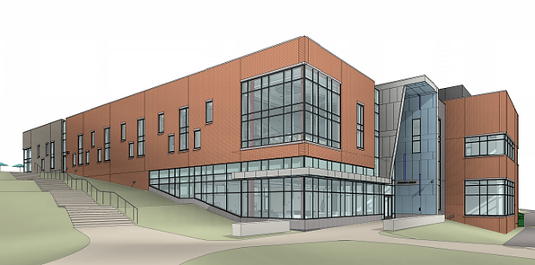
The envelope system for the Brandywine Student Union Building is consisted of four main elements; a brick veneer, a two-part curtain wall system (both vision glass and spandrel glass), a metal panel system, and a stone wall system. In combination with a fully-adhered EPDM roofing system on 1-½” 20 gage roof decking sloped at ¼” per 12”, this building strives to achieve LEED certification. Please see Figures A and B for an exterior rendering of the northeast corner and a typical roof assembly, respectively.
-
Figure A - Northeast Exterior Enclosure Rendering
-
Figure B - Typical EPDM Roof Section

Sustainability
-
This building, as you can see from Figure A, employs a substantial amount of natural light. The north side of the building, because it is opposite the natural sunlight, is consisted of brick and metal panels to limit cost, while the east, south, and west sides have a large amount of glazing, allowing natural sunlight to enter the spaces.
Building Statistics - Part II
Demolition and Excavation
-
The Student Union Building is one project on a two-project site, creating a difficult decision by the owner and their representative how to separate each project’s scope, if separating at all. The site is located on the west border of the property, with nothing but forest existing on site. Because of this, it made sense that the contract for the site work demolition be awarded to one contractor, while having every other element of the contracts be split based on a “divider” in the middle of the site. The site contract costed a total of $2.5M, including site electric. One important concern of this work was building a gravel pit in between the sites for storm water overflow. Raingardens were also considered, but decided that underground water storage for each individual project would be more beneficial. They began the site work on March 1, 2016 and the complete site work was ready for turnover by mid-June, 2016. See the figure below.

Construction
-
Notice to proceed was given on March 1, 2016, allowing the site work to begin on that date. The rest of the contracts were awarded the next two weeks, with shop drawings to be submitted by the 14th of March and be reviewed and approved by the 21st of March. Phase one of construction was sitework, which was originally to be completed by the end of March. However, setbacks developed when trying to obtain the building permit from the township, causing that date to be pushed to June 21st. Phase two was the actual construction of the building, with mini phases designated for equipment and material storage locations. This phase consists of setting the continuous strip footing foundation and piers, erecting structural steel, building the roof and exterior enclosure, and all of the interior work. It will last from June 22nd, 2016 until the Final Inspection / Punchlist on July 21st, 2017, approximately 13 months. The goal is to have the Certificate of Occupancy before the 2017 fall semester.
Mechanical
-
The main source of air is a combination of four (4) rooftop air handling units that supply the air to the building. There are two AHU’s at 15,000 CFM to provide cooling to the first and second floors, one AHU at 8,500 CFM for the cafeteria, and one make-up AHU at 6,500 CFM providing 100% outside air for cooling to the kitchen. VAV boxes in each space will have heating coils within to provide localized reheat. Circulation fans will be placed throughout larger spaces to provide proper air movement to meet specifications. There are six (6) pumps on the first floor to service two boilers, two hot water radiators, and two reheat hot water locations.
Structural
-
The Student Union Building has a fairly typical structural system consisting of concrete and structural steel. The support for the foundation are continuous strip footings 2’-0” x 1’-0” (some 2’-4” x 1’-0’) supporting 12” or 16” reinforced concrete precast foundation walls with column piers at each column location. The foundation 28-day compressive strength is set at 4,000psi. The first floor slab is a slab-on-grade construction, also at a 4,000psi compressive strength. The second floor is composite steel decking, with a compressive strength of 4,000psi. The composite decking for the second floor is a 5 ½” composite decking with 2” 19ga deck and 3 ½” lightweight concrete, while that of the roof is a 1 ½” 20ga roof decking.
-
The air handling units are located on the roof of this building, causing additional structural support to be in the roof design for each AHU. Along the perimeter of each RTU are W12x16 girders spanning the girders that are supporting the roofing system itself (either W21x44 or W21x55 on this side of the roof).
-
Another important item of concern within the structural system is the placing of the kitchen equipment on the second floor, which needed additional structural support. At these locations, the slabs are depressed from 4 – 8”, so additional W14x22 girders were installed for support.
Electrical
-
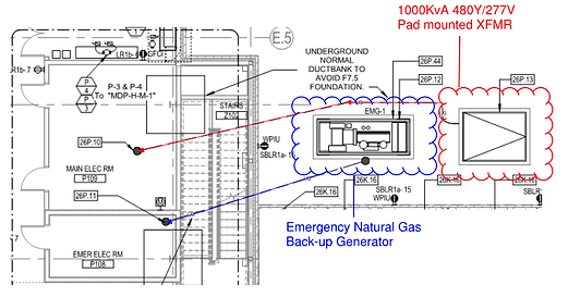
The electrical service to the building will be pulled from the existing main 15KV S&C vista switchgear. The power will be transferred to a 1000KvA pad-mounted transformer that is 3-phase and 4-wires 480Y/277 volt. From there, the power will be distributed via a 6-way underground ductbank from the outdoor transformer to an internal switchboard MDS located in the main electrical room, then transferred to 21 individual panelboards located throughout the building for localized power. There is also an emergency natural gas back-up generator located adjacent to the building and the main transformer. This generator has a 4-way underground ductbank from the generator to the emergency electrical room. See the following figure for more details.
Lighting
-
This building is separated into three main areas of occupancy. There are bookstore and gathering areas, a cafeteria and kitchen area, and office and meeting spaces. The bookstore contains mostly recessed 2’x2’ LED troffer fixtures with dimming features. Offices located on the first floor will have 4” wide by 6’ long recessed LED slot lighting also with dimming features. Meeting spaces larger than typical offices will contain slot lighting with LED downlighting at each end and midpoint of each 2” recessed LED slot. In the service areas, the fixtures will be 4’ long industrial fluorescent lighting with no dimming abilities. The lighting in the kitchen area will be 2’x4’ recessed LED troffers, with occasional 4’ long industrial fluorescent lighting. In the cafeteria area however, the majority of the fixtures will be 4” to 6” recessed LED downlighting with dimming capabilities.
-
The majority of the controls within in this building, including the bookstore and cafeteria, will be a manual on/off switch with occupancy sensors. Offices will have localized dimming, and the meeting rooms will have localized dimming with a multi-scene controller. The only automatic switches are in the main areas, such as the corridors, vestibules and lobbies. Stairwells will have 100% on occupancy, dimmed to 50% upon vacancy.